#PQ092
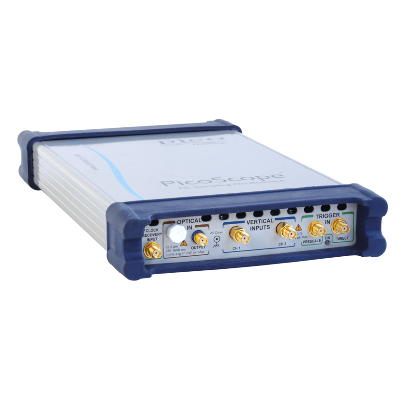
PicoScope 9300 Series - 2Ch, 20GHz, CR, OI
Product Description
- Up to 30 GHz bandwidth
- Electrical, optical, TDR/TDT and 4-channel models
- 15 TS/s (64 fs) sequential sampling, display resolution to 640 TS/s (1.5 fs)
- Up to 15 GHz prescaled, 2.5 GHz direct trigger and 11.3 Gb/s clock recovery
- Industry-leading 16-bit 1 MS/s ADC and 60 dB dynamic range
- Intuitive, touch-compatible Windows user interface
- Comprehensive built-in measurements, histogramming and editable data mask library
- Integrated, differential, deskewable TDR/TDT step generator
Specifications
| Oscilloscope – vertical (analog) | 9300-20 models | 9300-30 models | |
|---|---|---|---|
| Number of channels | PicoScope 9341: 4 All other models: 2 | ||
| Acquisition timing | Selectable simultaneous or alternate acquisition | ||
| Bandwidth, Full | 20 GHz | 30 GHz | |
| Bandwidth, Mid | N/A | 20 GHz | |
| Bandwidth, Narrow | 10 GHz | 12 GHz | |
| Pulse response rise time, full bandwidth | 17.5 ps (10% to 90%, calculated) | 14.0 ps (10% to 90%, calculated) | |
| Pulse response rise time, narrow bandwidth | 35.0 ps (10% to 90%, calculated) | 29.2 ps (10% to 90%, calculated) | |
| Noise, full bandwidth | < 1.5 mV RMS typical, < 2.0 mV RMS maximum | < 1.9 mV RMS typical, < 2.5 mV RMS maximum | |
| Noise, narrow bandwidth | < 0.8 mV RMS typical, < 1.1 mV RMS maximum | < 1.0 mV RMS typical, < 1.3 mV RMS maximum | |
| Noise with averaging | 100 μV RMS system limit, typical | ||
| Operating input voltage with digital feedback | 1 V p-p with ±1 V range (single-valued) | ||
| Operating input voltage without digital feedback | ±400 mV relative to channel offset (multi-valued) | ||
| Sensitivity | 1 mV/div to 500 mV/div in 1-2-5 sequence with 0.5% fine increments | ||
| Resolution | 16 bits, 40 μV/LSB | ||
| Accuracy | ±2% of full scale ±2 mV over nominal temperature range (assuming temperature-related calibrations are performed) | ||
| Nominal input impedance | (50 ±1) Ω | ||
| Input connectors | 2.92 mm (K) female, compatible with SMA and PC3.5 | ||
| Timebase (Sequential time sampling mode) | |
|---|---|
| Ranges | 5 ps/div to 3.2 ms/div (main, intensified, delayed, or dual delayed) |
| Delta time interval accuracy | For > 200 ps/div: ±0.2% of delta time interval ± 12 ps For < 200 ps/div: ±5% of delta time interval ± 5 ps |
| Time interval resolution | 64 fs |
| Channel deskew | 1 ps resolution, 100 ns max. |
| Triggers | |||
|---|---|---|---|
| Trigger sources | All models: external direct, external prescaled, internal direct and internal clock triggers. PicoScope 9302 and 9321 only: external clock recovery trigger | ||
| External direct trigger bandwidth and sensitivity | DC to 100 MHz : 100 mV p-p; to 2.5 GHz: 200 mV p-p | ||
| External direct trigger jitter | 1.8 ps RMS (typ.) or 2.0 ps RMS (max.) + 20 ppm of delay setting | ||
| Internal direct trigger bandwidth and sensitivity | DC to 10 MHz: 100 mV p-p; to 100 MHz: 400 mV p-p (channels 1 and 2 only) | ||
| Internal direct trigger jitter | 25 ps RMS (typ.) or 30 ps RMS (max.) + 20 ppm of delay setting (channels 1 and 2 only) | ||
| External prescaled trigger bandwidth and sensitivity | 1 to 14 GHz, 200 mV p-p to 2 V p-p | 1 to 14 GHz, 200 mV p-p to 2 V p-p 14 to 18 GHz, 500 mV p-p to 2 V p-p | |
| External prescaled trigger jitter | 1.8 ps RMS (typ.) or 2.0 ps RMS (max.) + 20 ppm of delay setting | ||
| Pattern sync trigger clock frequency | 10 MHz to 14 GHz | 10 MHz to 18 GHz | |
| Pattern sync trigger pattern length | 7 to 8 388 607 (223− 1) | ||
| Clock recovery (PicoScope 9302 and 9321) | |
|---|---|
| Clock recovery trigger data rate and sensitivity | 6.5 Mb/s to 100 Mb/s: 100 mV p-p >100 Mb/s to 11.3 Gb/s: 20 mV p-p |
| Recovered clock trigger jitter | 1 ps (typ.) or 1.5 ps (max.) + 1.0% of unit interval |
| Maximum safe trigger input voltage | ±2 V (DC + peak AC) |
| Input characteristics | 50 Ω, AC coupled |
| Input connector | SMA (F) |
| Acquisition | |
|---|---|
| ADC resolution | 16 bits |
| Digitizing rate with digital feedback (single-valued) | DC to 1 MHz |
| Digitizing rate without digital feedback (multi-valued) | DC to 40 kHz |
| Acquisition modes | Sample (normal), average, envelope |
| Data record length | 32 to 32 768 points (single channel) in x2 sequence |
| Display | |
|---|---|
| Styles | Dots, vectors, persistence, gray-scaling, color-grading |
| Persistence time | Variable or infinite |
| Screen formats | Auto, single YT, dual YT, quad YT, XY, XY + YT, XY + 2 YT |
| Measurement and analysis | |
|---|---|
| Markers | Vertical bars, horizontal bars (measure volts) or waveform markers |
| Automatic measurements | Up to 10 at once |
| Measurements, X parameters | Period, frequency, pos/neg width, rise/fall time, pos/neg duty cycle, pos/neg crossing, burst width, cycles, time at max/min, pos/neg jitter ppm/RMS |
| Measurements, Y parameters | Max, min, top, base, peak-peak, amplitude, middle, mean, cycle mean, AC/DC RMS, cycle AC/DC RMS, pos/neg overshoot, area, cycle area |
| Measurements, trace-to-trace | Delay 1R-1R, delay 1F-1R, delay 1R-nR, delay 1F-nR, delay 1R-1F, delay 1F-1F, delay 1R-nF, delay 1F-nF, phase deg/rad/%, gain, gain dB |
| Eye measurements, X NRZ | Area, bit rate, bit time, crossing time, cycle area, duty cycle distortion abs/%, eye width abs/%, rise/fall time, frequency, period, jitter p-p/RMS |
| Eye measurements, Y NRZ | AC RMS, average power lin/dB, crossing %/level, extinction ratio dB/%/lin, eye amplitude, eye height lin/dB, max/min, mean, middle, pos/neg overshoot, noise p-p/RMS one/zero level, p-p, RMS, S/N ratio lin/dB |
| Eye measurements, X RZ | Area, bit rate/time, cycle area, eye width abs/%, rise/fall time, jitter p-p/RMS fall/rise, neg/pos crossing, pos duty cycle, pulse symmetry, pulse width |
| Eye measurements, Y RZ | AC RMS, average power lin/dB, contrast ratio lin/dB/%, extinction ratio lin/dB/%, eye amplitude, eye high lin/dB, eye opening, max, min, mean, middle, noise p-p/RMS one/zero, one/zero level, peak-peak, RMS, S/N |
| Histogram | Vertical or horizontal |
| Math functions | |
|---|---|
| Mathematics | Up to four math waveforms can be defined and displayed |
| Math functions, arithmetic | +, −, ×, ÷, ceiling, floor, fix, round, absolute, invert, (x+y)/2, ax+b |
| Math functions, algebraic | ex, ln, 10x, log10, ax, loga, d/dx, integrate, x2, sqrt, x3, xa, x−1, sqrt(x2 +y2) |
| Math functions, trigonometric | sin, sin−1, cos, cos−1, tan, tan−1, cot, cot−1, sinh, cosh, tanh, coth |
| Math functions, FFT | Complex FFT, complex inverse FFT, magnitude, phase, real, imaginary |
| Math functions, combinatorial logic | AND, NAND, OR, NOR, XOR, XNOR, NOT |
| Math functions, interpolation | Linear, sin(x)/x, trend, smoothing |
| Math functions, other | Custom formula |
| FFT | Up to two FFTs simultaneously |
| FFT window functions | Rectangular, Hamming, Hann, flat-top, Blackman–Harris, Kaiser–Bessel |
| Eye diagram | Automatically characterizes NRZ and RZ eye patterns based on statistical analysis of waveform |
| Mask tests | |
|---|---|
| Mask geometry | Acquired signals are tested for fit outside areas defined by up to eight polygons. Standard or user-defined masks can be selected. |
| Built-in masks, SONET/SDH | OC1/STMO (51.84 Mb/s) to FEC 1071 (10.709 Gb/s) |
| Built-in masks, Ethernet | 1.25 Gb/s 1000Base-CX Absolute TP2 to 10xGB Ethernet (12.5 Gb/s) |
| Built-in masks, Fibre Channel | FC133 (132.8 Mb/s) to 10x Fibre Channel (10.5188 Gb/s) |
| Built-in masks, PCI Express | R1.0a 2.5G (2.5 Gb/s) to R2.1 5.0G (5 Gb/s) |
| Built-in masks, InfiniBand | 2.5G (2.5 Gb/s) to 5.0G (5 Gb/s) |
| Built-in masks, XAUI | 3.125 Gb/s |
| Built-in masks, RapidIO | Level 1, 1.25 Gb/s to 3.125 Gb/s |
| Built-in masks, SATA | 1.5G (1.5 Gb/s) to 3.0G (3 Gb/s) |
| Built-in masks, ITU G.703 | DS1 (1.544 Mb/s) to 155 Mb (155.520 Mb/s) |
| Built-in masks, ANSI T1.102 | DS1 (1.544 Mb/s) to STS3 (155.520 Mb/s) |
| Built-in masks, G.984.2 | XAUI-E Far (3.125 Gb/s) |
| Built-in masks, USB | USB 3.0 (5 Gb/s), USB 3.1 (10 Gb/s) |
| Signal generator output | |
|---|---|
| Modes | Pulse, PRBS NRZ/RZ, 500 MHz clock, trigger out |
| Period range, pulse mode | 8 ns to 524 μs |
| Bit time range, NRZ/RZ mode | 4 ns to 260 μs |
| NRZ/RZ pattern length | 27−1 to 215−1 |
| TDR pulse outputs | PicoScope 9311-20 | |
|---|---|---|
| Number of output channels | 2 (1 differential pair) | |
| Output enable | Independent or locked control for each source | |
| Pulse polarity | Channel 1: positive-going from zero volts Channel 2: negative-going from zero volts | |
| Rise time (20% to 80%) | 60 ps guaranteed | |
| Amplitude | 2.5 V to 7 V into 50 Ω | |
| Amplitude adjustment | 5 mV increments | |
| Amplitude accuracy | ±10% | |
| Offset | ||
| Output amplitude safety limit | Adjustable from 2.5 V to 8 V | |
| Output pairing | Amplitudes and limit paired or independent | |
| Period range | 1 μs to 60 ms | |
| Period accuracy | ±100 ppm | |
| Width range | 200 ns to 4 μs, 0% to 50% duty cycle | |
| Width accuracy | ±10% of width ±100 ns | |
| Deskew between outputs | −1 ns to +1 ns typical, in 1 ps increments | |
| Timing modes | Step, coarse timebase, pulse | |
| Impedance | 50 Ω | |
| Connectors on scope | SMA(f) x 2 | |
| TDR pre-trigger output | ||
|---|---|---|
| Polarity | Positive-going from zero volts | |
| Amplitude | 700 mV typical into 50 Ω | |
| Pre-trigger | 25 ns to 35 ns typical, adjustable in 5 ps increments | |
| Pre-trigger to output jitter | 2 ps max. | |
| TDT system | PicoScope 9311-20 | |
|---|---|---|
| Number of TDT channels | 2 | |
| Incident rise time (combined oscilloscope and pulse generator, 10% to 90%) | 60 ps or less, each polarity | |
| Jitter | 3 ps + 20 ppm of delay setting, RMS, max. | |
| Corrected rise time | Min. 50 ps or 0.1 x time/div, whichever is greater, typical Max. 3 x time/div, typical | |
| Corrected aberrations | = 0.5% typical | |
| TDR system | PicoScope 9311-20 | |
|---|---|---|
| Number of channels | 2 | |
| Incident rise time (combined oscilloscope, step generator and TDR kit, 10% to 90%) | s60 ps or less, each polarity | |
| Reflected step amplitude, from short or open | 25% of input pulse amplitude, typical | |
| Reflected rise time (combined oscilloscope, step generator and TDR kit, 10% to 90%) | 60 ps or less @ 50 Ω termination, each polarity | |
| Corrected rise time | Minimum: 50 ps or 0.1 x time/div, whichever is greater, typical. Maximum: 3 x time/div, typical. | |
| Corrected aberration | ≤ 1% typical | |
| Measured parameters | Propagation delay, gain, gain dB | |
| TDR/TDT scaling | |
|---|---|
| TDT vertical scale | volts, gain (10 m/div to 100 /div) |
| TDR vertical scale | Volts, rho (10 mrho/div to 2 rho/div), ohm (1 ohm/div to 100 ohm/div) |
| Horizontal scale | Time (800 ns/div max.) or distance (meter, foot, inch) |
| Distance preset units | Propagation velocity (0.1 to 1.0) or dielectric constant (1 to 100) |
| Optical/electrical converter (PicoScope 9321-20) | |
|---|---|
| Bandwidth (−3 dB) | 9.5 GHz typical |
| Effective wavelength range | 750 nm to 1650 nm |
| Calibrated wavelengths | 850 nm (MM), 1310 nm (MM/SM), 1550 nm (SM) |
| Transition time | 51 ps typical (10% to 90% calculated from tR = 0.48/optical BW) |
| Noise | 4 μW (1310 & 1550 nm), 6 μW (850 nm) maximum @ full electrical bandwidth |
| DC accuracy | ±25 μW ±10% of full scale |
| Maximum input peak power | +7 dBm (1310 nm) |
| Fiber input | Single-mode (SM) or multi-mode (MM) |
| Fiber input connector | FC/PC |
| Input return loss | SM: −24 dB typical MM: −16 dB typical, −14 dB maximum |
| General | |
|---|---|
| Temperature range, operating | +5 °C to +35 °C |
| Temperature range for stated accuracy | Within 2 °C of last autocalibration |
| Temperature range, storage | −20 °C to +50 °C |
| Calibration validity period | 1 year |
| Power supply voltage | +12 V DC ± 5% |
| Power supply current | 1.7 A max. |
| Mains adaptor | Universal adaptor supplied |
| PC connection | USB 2.0 (compatible with USB 3.0) |
| LAN connection | 10/100 Mbit/s |
| PC requirements | Microsoft Windows XP, 7, 8, or 10 32‑bit or 64‑bit versions. |
| Dimensions | 170 mm x 285 mm x 40 mm (W x D x H) |
| Weight | 1.3 kg max. |
| Compliance | CE (EMC and LVD) |